


 66 / 92

66
Dossier
|
Insitu N20 UAV 50 cc two-stroke single
the tank once a given pressure has
been obtained. This system has the
effect of warming the fuel, which helps
overcome the problem of waxing when
using kerosene-based fuel at very low
temperatures in flight.
Fuel delivery pressure is a function of
the regulated pressure created by the
delivery pump and the fuel regulator,
which can be anything up to 6.5 bar,
which is referenced (or related to) the
pressure of the compressed air supply,
which is normally in the region of 4 bar.
The compressed air is supplied by
a crankshaft-driven air compressor,
which uses a piston pump. Matching the
reciprocation of the combustion piston, the
air compressor piston supplies a given
amount of air at any given engine speed.
The increase in air supply with
increasing rpm is not a linear
relationship, given the design of the
porting that transfers air from the
crankcase into the piston pump working
chamber. Moreover, the air supply system
has an accumulator effect, such that the
compressed air supply is at constant
pressure rather than pulsed.
On the ignition side, while the N20 has
provision for a second spark plug, that is
not the initial offering – it is in recognition
of the fact that in some instances it will
be a requirement of certification. The
long-life iridium spark plug is fired by
a high-energy, long-duration inductive
coil. The coil is directly fired by the ECU,
which determines spark timing and dwell,
thereby controlling ignition energy.
In theory the coil – or pair of coils in
the case of a twin-plug arrangement –
could be directly mounted on the plug,
but in practice it is remotely located for
reason of overall craft streamlining.
N20 mechanicals
The N20 features a single-piece cantilever-
mounted crankshaft in a one-piece
crankcase (in other words, it is supported
only on the drive side of the crankpin). The
crankcase has a rear panel for access,
which houses the reed valve.
The propeller is directly driven by
the front of the longitudinally oriented
crankshaft (with main bearings between
it and the crankpin). The terms ‘front’ and
‘rear’ refer to use in a puller configuration;
as noted, in the ScanEagle the N20 is
swapped around to work as a pusher.
A generator fits onto the front of the
crankshaft, just behind the propeller,
which is bolted to its rotor. Integral with
the crankcase is the housing for the air
compressor, which is located between
the generator and the power cylinder. An
eccentric lobe on the crankshaft drives
the piston used for air compression.
This is sandwiched by the two main
bearings (a roller and a ball bearing).
The big-end bearing is of the roller type,
and Cathcart recognises that the fact
the crankpin is cantilevered “avoids the
need for a split crankcase that can be the
source of a leak”.
The cylinder head is integral with the
barrel, which makes plating and honing
the bore more challenging. However, the
base of the cylinder can then be formed
as a flange with four short bolts attaching
it to the top of the crankcase.
The combined head and barrel thus
saves the weight of head bolts as well
as of a head sealing system, and where
it attaches via its flange to the crankcase
is a low-pressure seal, so an O-ring
suffices. The only gasket in the engine
is that of the exhaust, which is pressed
metal stainless steel with a two-bolt fixing.
The single crankshaft web has a heavy
metal plug for reason of counterbalance;
the balance factor is undisclosed.
Cathcart notes that the air compressor
lobe incorporated into the crankshaft
and the generator’s rotor contribute to
engine balance. “The air compressor
and the rotor help minimise the vibration
couple,” he says.
The con rod is of tapered section since
that type is considered to minimise weight
while maximising stiffness and durability.
The rod is hardened steel, forged and
machined, and the big-end bearing
runs directly in it, as does a needle roller
bearing in the small end. Enhanced
lubrication for the big or small end is not
considered necessary, as both are served
by general oil mist in the crankcase.
The piston pin is hardened steel,
machined from solid and through-
drilled with tapered ends to the drilling.
Uncoated, the pin runs directly in the
small-end bearing and in the piston. The
pin is retained by steel wire C-clips, which
are a sufficiently tight fit in the respective
pin bore groove to stop rotation of them,
although the pin itself rotates.
The piston is described as “die cast
from a high silicon-aluminium alloy”, the
actual percentage of silicon being
June/July 2016 |
Unmanned Systems Technology
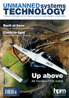
ScanEagle launch – field testing the N20