


 25 / 92

25
recovery at the wingtips, maximising
efficiency for a given span and root
bending moment. They are heavily raked
to maintain attached flow through partial
vortex lift at high wing loadings,” de
Villiers says.
Several aerofoil sections with different
thickness-to-chord ratios at different
positions along the span help to optimise
the behaviour of the structure under
aerodynamic loads. The aerofoil sections
are drawn from a library and customised
to form the final design, this detailed work
having been carried out by D3 Applied
Technologies, which Carbonix describes
as a leading aero optimisation team.
As standard, the winglets are integral
with the wing, but they can be made as
separate detachable parts as an option.
Again as standard, they are made
from carbon fibre-reinforced epoxy, but
the customer can specify glass fibre
reinforcement to make them transparent
to radio signals so that they can house
antennae. The transition to glass happens
seamlessly at the lay-up stage, so that
the structure remains continuous.
The fuselage cross-section is essentially
trapezoidal, a shape selected to maximise
internal volume while keeping drag-
inducing wetted area (skin exposed to the
airflow) to a minimum. It has a flat bottom
and vertical sides that taper inboard as
they go up to meet the wing, while the
fillet between bottom and sides is varied
along the length of the fuselage. Tapering
the fuselage cross-section below the wing
helps to manage pressure distribution
in a manner analogous to the area rule,
although strictly that rule applies at much
higher speeds.
“This is an example of a detail that
called for specialised expertise in tooling
design, to allow the fuselage and wing
roots to be moulded in one piece and
still be released from the mould,” says
Dario Valenza of Carbonix.
Structural members
The central fuselage and blended wing
route moulding features a bonded-in
tubular carry-through spar, while the
outer wing sections each have a single
spar that consists of a transverse foam
sandwich panel with carbon shear webs
and a foam core.
“During development of the airframe
we experimented with different solutions,
such as a moulded I-beam spar
laminated into the structure, and a
Nomex honeycomb panel construction,”
says de Villiers. “The current
configuration reflects the best trade-off
between structural efficiency, toughness
and cost.”
The central fuselage and wing root
structure is a moulded stressed-skin
monocoque with optimised fibre layout
and patching, and the carry-through
spar is bonded in while the fuselage
skins are in the mould. Other integral
structural components include the
engine bulkhead, a ring frame to locate
the motor controls and what de Villiers
describes as a partial bulkhead that
doubles as the front end of the fuel tank.
The top of the tank also forms part of
the payload shelf. Making every piece of
structure serve more than one purpose in
this way minimises weight and maximises
structural efficiency, he says.
Unmanned Systems Technology
| June/July 2016
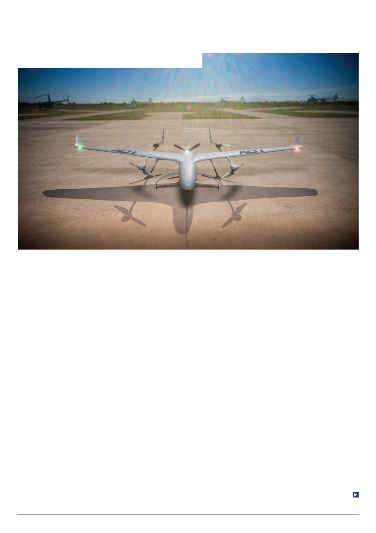
Transition sits on its fixed gear, the lack of wheels emphasising that it is a VTOL-
only machine. The front two legs are shaped to help generate lift in forward flight