


 36 / 92

36
this requires additional power. That then
drives the demand for a truck with a
back-up generator.
Control
One issue faced by GCS designers is
the need to simplify the user interface for
controlling the craft. An implementation
with two joysticks is common, each with
three-axis control with up to 36 switches
that can be used as a remote control for
the craft and the camera system.
The function of these switches can
be modified through the Windows USB
interface to map onto specific autopilot
functions such as rudder, aileron
and thrust control; the more switches
available the finer the control can be.
Some GCSs also provide switches that
can be customised for functions such as
triggering a UAV parachute at the end
of a mission. All of this is easily handled
within the Windows environment.
The control of the gimbal for the
camera uses a serial connection from the
autopilot. In this scenario the data links
have a couple of pass-throughs, so one
serial connection is used for the autopilot
and telemetry, and the other to control
the gimbal by moving it with the joystick.
This shows how important it is to
have all the external interfaces available
– the LAN/Ethernet port, serial lines,
external power, USB ports to download
maps or videos, and the HDMI port to
deliver video to a big screen or on to a
command and control centre.
Communications
The comms with a UAV is another area
where the base GCS is modified. These
connections can be standard 2.4 GHz
links or use other frequencies chosen
by the UAV supplier or the customer.
The comms boards are mounted inside
the GCS, with a heat sink and wiring
to connect the antenna, plus a digital
switch between external directional and
omnidirectional antennae.
GCS manufacturers will leave an
empty space inside the box for the end-
user to install their own data links so
that the same generic system can be
used with UAVs, ground robots for mine
clearance or other surface vehicles that
run via fibre optic control, for example. All
the changes are handled in the software,
saving cost and integration time.
For long-range UAV systems that
travel beyond the line of sight, using an
external antenna that can be moved to
follow the craft in the air allows different
comms protocols and frequencies to
be used by just changing the interface
board. Simpler systems with an internal
or fixed antenna are restricted to a
certain set of frequencies, and this often
then also determines which protocols
can be used.
For example, wi-fi or Bluetooth only
operate at 2.4 GHz, while other links
have a longer range with the 868 MHz or
915 MHz bands, but these require larger
antennae and carry less data. Directional
antennae can be used with other
frequencies such as S band at 2.1-2.3
GHz and go up to C band at 4-5 GHz.
The choice of frequency and protocol
comes down to the customer’s
requirements, and requires the GCS
developer to modify the antenna. As a
result, a flexible ground station needs
to be able to support this range of
antennae and radio protocol boards via
the PC port.
It also means having different voltages
– 5, 12, 24 and 28 V – to power the
antennae and the boards, and provide
flexibility for the operator.
Adding the antenna system with a
mast-based, pan-and-tilt dish antenna
brings some other subtleties. Placing
the RF linear power amplifiers on the
antenna side means the coax cables
from the dish are as short as
June/July 2016 |
Unmanned Systems Technology
Focus
|
Ground control systems
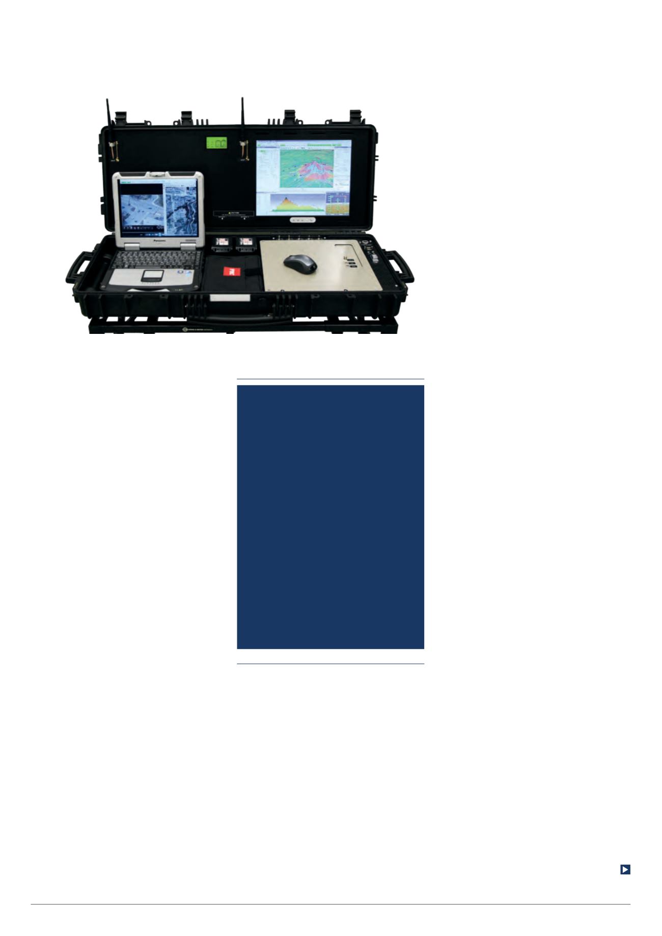
A dual-screen GCS allows mapping and
payload data to be handled separately for
longer missions (Courtesy of UAV Factory)
Manufacturers
will leave an
empty space
inside the GCS
box for the user
to install their
own data links for
a generic system